|
|
August 14, 1999
Step 4: The Light Board
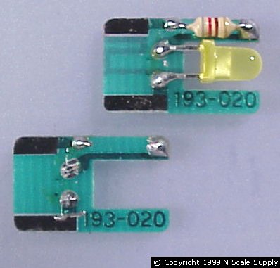
The GP20 is equipped with two light boards. Take one and cut all of the components off of it as in the picture below. Please note that I replaced the headlight with a Miniatronics 1.5volt bulp to give the headlight a more natural color. It would also be possible to leave the LED in place, cut the PC Board traces to it and utilize it as well.

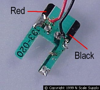
Next cut the Red, Black, White and Blue leads of the decoder about 1-3/4" in length ( a little long won't hurt). Solder these to the ends of the pads as shown below. Try to keep the solder off of the main part of the pads so the board will slide back into the frame.

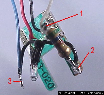
Cut the leads on the Miniatronics bulb at about a 1/2" to 5/8" in length. Solder one lead to the Blue wire ( #3 in picture). It is necessary to use a 560ohm resistor to keep the bulb from burning out. Clip the leads on the resistor very short, just enough to attach the wire leads. Solder the remaining lead of the bulb to one end ( #2 in picture), the White decoder lead to the other ( #1 in picture). I soldered the resistor to the end of the light board to hold it in place.

Using a small strip of Kapton tape, attach the blue/black solder joint to the light board where it says 3-020.